https://www.thethingsnetwork.org/forum/t/big-esp32-sx127x-topic-part-1/10247
https://www.thethingsnetwork.org/forum/t/big-esp32-sx127x-topic-part-2/11973
The ESP32 MCU and SX127x / RFM9x LoRa transceiver
The ESP32 has built-in support for Wifi and Bluetooth communication but not for LoRa. A SX127x or RFM9x LoRa transceiver adds support for LoRa and the LoRaWAN protocol that are needed for The Things Network.
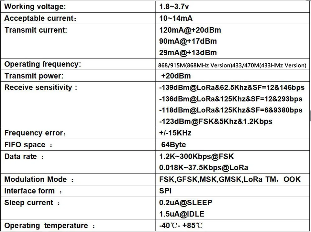
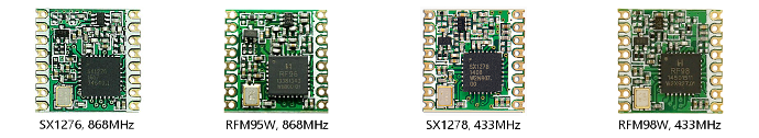
Semtech SX127x LoRa transceivers and HopeRF RFM9x LoRa transceivers are identical. They come in different variants, depending on the targeted frequency band (433, 868 and 915 MHz). Which frequencies are used depends on the geographic region and local ISM band regulations. (HopeRF module numbers usually end with W which stands for ‘international version’.)
The ESP32 and the LoRa transceivers come in several forms:
- On modules.
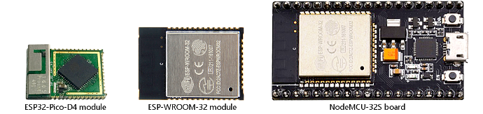
Modules contain additional components required for making the chips work. The modules use 1.27mm or 2mm pin spacing. For use with breadboards and prototyping PCB with 2.54mm spacing adapters are required. Examples: ESP-WROOM-32 ESP32 module, SX1276 and RFM95 LoRa modules.
- On development boards.
Development boards (often) convert to 2.54mm spacing and add additional functionality like power converter, buttons and LEDs. Development boards use either standard modules or separate components. Examples: ESP32 Dev board, Lolin32 and NodeMCU-32S. A pure adapter is the HopeRF RFM95 adapter.
- On custom boards which combine ESP32 with a LoRa transceiver.
Custom boards can use standard modules, separate components or a combination of both.
Examples: Heltec Wifi LoRa 32 and TTGO LoRa32.
Software
In addition to the hardware, software is needed for implementing the LoRaWAN protocol. The SX127x LoRa tranceiver provides LoRa radio modulation but it does not implement the LoRaWAN protocol. The protocol has to be implemented in software that needs to run on the ESP32.
The following library implements a LoRaWAN protocol stack that can be used with ESP32:
LMIC-Arduino.
The LMIC-Arduino library can be found here:
https://github.com/matthijskooijman/arduino-lmic6The library contains examples for implementing a Things Network node for both ABP and OTAA activation.
Try to get the ttn-abp.ino example working first. If that works continue with the ttn-otaa.ino example. When both these examples work then the LoRaWAN part of your setup works. From there you can start adding additional features (e.g. temperature sensor) but get the basics working first.
ABP and OTAA require different settings. See TTN Console and remarks in the sketches for more information.
A nice library for (on-board) (OLED) monochrome displays is:
U8g2The U8g2 library can be found here:
https://github.com/olikraus/u8g22(U8g2 includes U8x8 which is lower on resources.)
ESP32 + SX127x/RFM9x can also be used for implementing a Single Channel Gateway. Information about the Single Channel Gateway software can be found in the following topic:
Single Channel Gateway part 3(See ‘List of single channel gateway implementations / For ESP32’.)
Popular ESP32 LoRa boards
The following boards are popular for prototyping because they combine an ESP32, a LoRa tranceiver, an OLED 128x64 display and LiPo/Li-Ion battery support with charging in one small package that can be used on a breadboard:
- Heltec Wifi LoRa 32
- TTGO LoRa32
They come in several different versions and there are separate versions for 433/470MHz and 868/915MHz.
LoRa antenna: external, connected via cable with I-PEX connector; 868MHz have 5cm external whip antenna with SMA connector; 433MHz have a helical wire antenna.
WiFi/Bluetooth antenna: single on-board antenna
(performance is sub-optimal).
Battery connector: 2-pin
Molex PicoBlade1 (1.25mm spacing). Compatible connectors: ‘JST 1.25mm’ sold on
AliExpress2 and eBay
(sold as JST-PH 1.25mm but it is not PH because PH uses 2.0mm spacing).
Be careful with cables that were not included with the board: check first if the colors match the polarity of the board, reversing battery polarity may destroy the board.
There is a dedicated LED (non-programmable) for the battery. It is on when the battery is charged. When no battery is connected: it is off when powered via 3.3V pin but flashes when powered via USB or 5V pin.
A second LED (white on Heltec, blue on TTGO) (programmable) is connected to pin 25.
There have been issues with some pigtail cables and some TTGO boards where components were not properly soldered. For more information about these issues check part 1 of this topic.
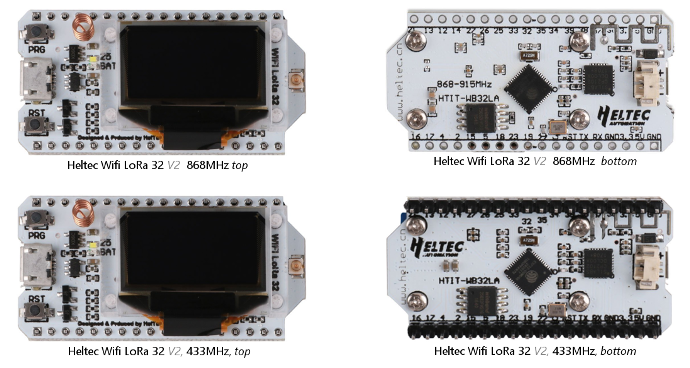
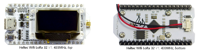
Heltec Wifi LoRa 32
Have a white PCB and come in two different versions (the version numbers are not used by Heltec):
- V1: with on-board PCB WiFi/Bluetooth antenna. Appears to be available for 433MHz only.
- V2: with small on-board helical antenna (has a PCB antenna on the bottom but that is not connected).
Pinout diagram6.
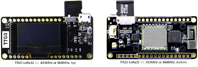
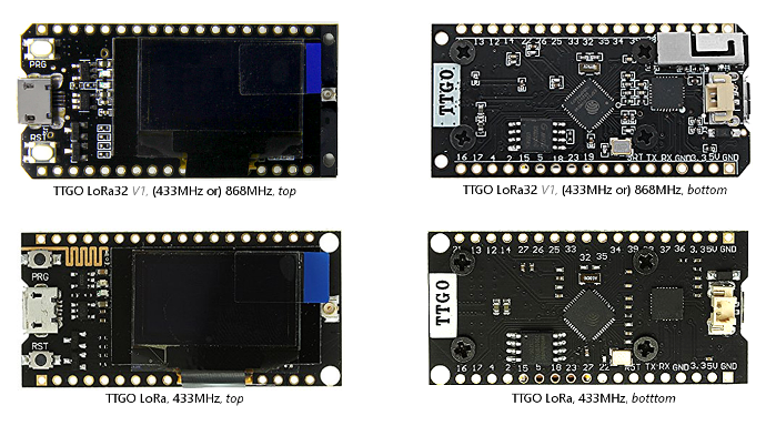
TTGO LoRa32
Have a black PCB and come in several different versions:
- LoRa (without 32): with on-board PCB Wifi/Bluetooth antenna on top. Appears to be available for 433MHz only. Also available without the display.
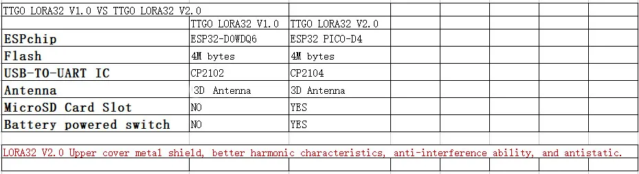
- LoRa32 V1: with on-board metal Wifi/Bluetooth antenna on bottom. I-Pex connector located on top.
- LoRa32 V2: with on-board metal Wifi/Bluetooth antenna on bottom (in a different location).
Uses ESP32-Pico-D4 (with integrated flash memory) instead of ESP32, uses a (shielded) LoRa module, I-Pex connector located on the bottom, micro-USB connector is rotated 90 degrees, in addition has a micro-SD card slot on the bottom and an on/off switch for the battery next to the micro-USB connector. According to the ESP32-Pico-D4 datasheet3 a micro-SD card is accessible for code and data but data can only be read, not written. Pinout diagram3. The LoRa modules appear to be HPD13A and HPD14A from HPDTek.
PIN Mappings
PIN mappings that are already correctly defined in the ‘Heltec Wifi LoRa 32’ board definition for Arduino are:
LED_BUILTIN=25, SCK=5, MOSI=27, MISO=19, SS=18
For the SX127x/RFM9x LoRa transceiver use:
RST: 14, NSS: 18, SCK: 5, MOSI: 27, MISO: 19, DIO0: 26, DIO1: 33, DIO2: 32
(DIO0 is called IRQ in several pinout diagrams and DIO1 and DIO2 are not mentioned).
For the SSD1306 OLED display use (note: the I2C pins are non-standard):
SCL: 15, SDA: 4, RST: 16
In software:
const lmic_pinmap lmic_pins = {
  .nss = SS,  //18
  .rxtx = LMIC_UNUSED_PIN,
  .rst = 14,
  .dio = {/*dio0*/ 26, /*dio1*/ 33, /*dio2*/ 32}
};

...

//Custom pin numbers are not required when the Heltec Wifi LoRa 32 board is selected
SPI.begin(/*sck*/ 5, /*miso*/ 19, /*mosi*/ 27, /*ss*/ 18);

...

//For the display use:
//(See U8x8/U8g2 documentation for display write functions)
#include <U8x8lib.h>
U8X8_SSD1306_128X64_NONAME_SW_I2C display(/*scl*/ 15, /*sda*/ 4, /*rst*/ 16);
display.begin();
display.setFont(u8x8_font_victoriamedium8_r);
Example hardware
Below pictures show an overview of available hardware and their appearance. All pictures have the same size ratio for a realistic comparison.
ESP32 modules / boards
LoRa Tranceiver modules
Heltec boards
TTGO boards